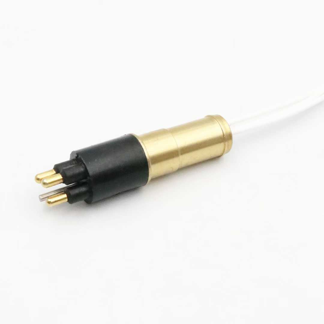
IEB4F 4-Channel Female EO Wet-Mate Underwater Fiber Optic Connector
Product Overview
The
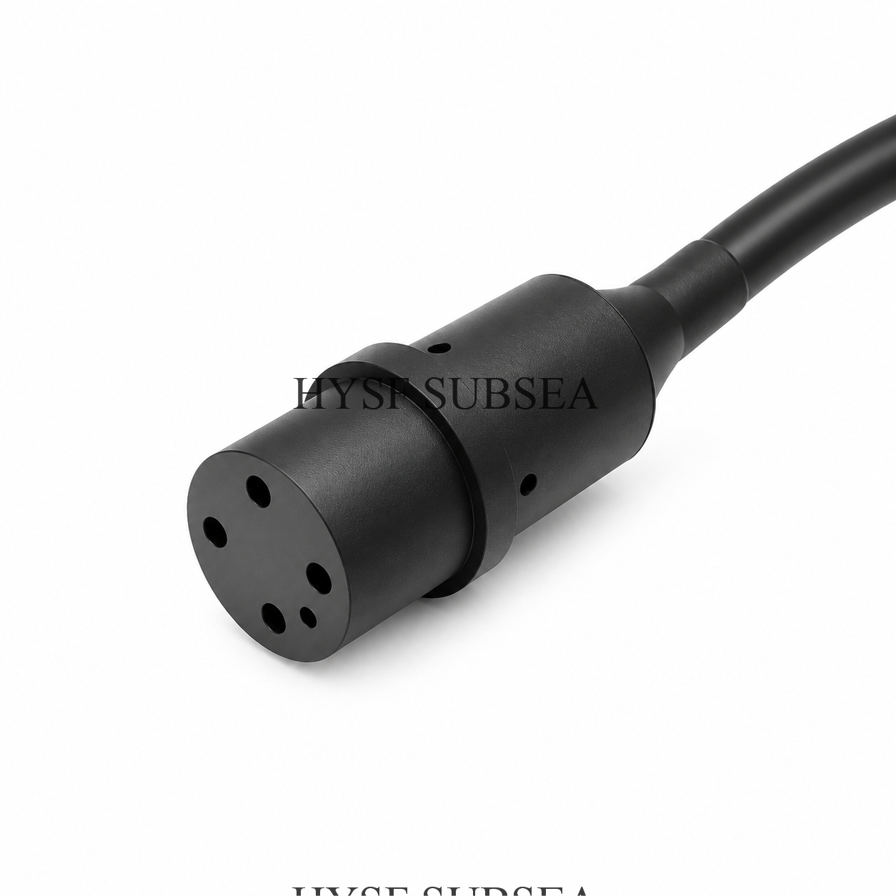
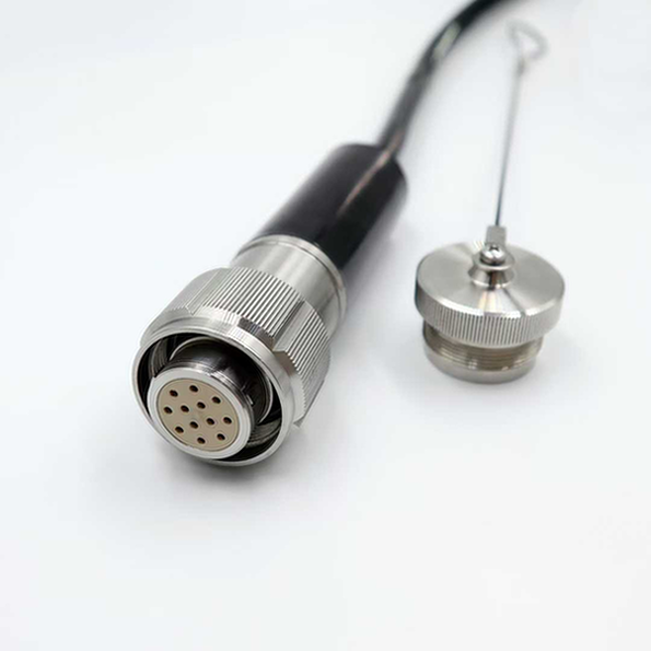
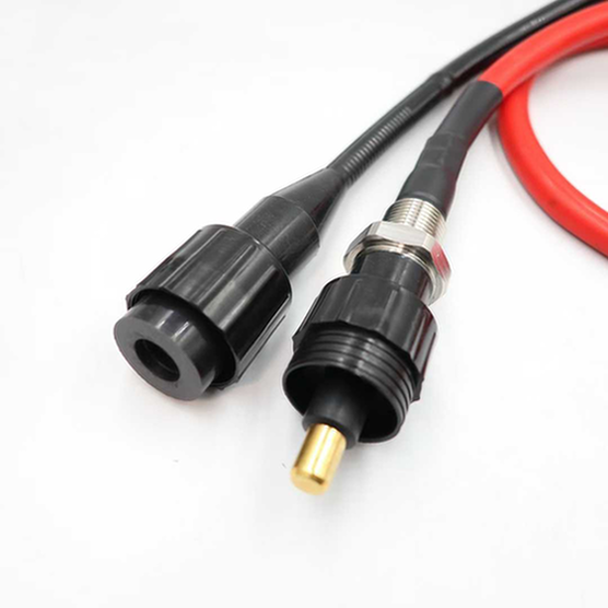
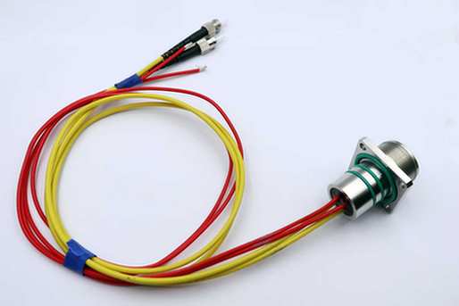
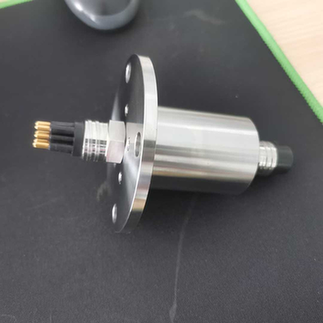
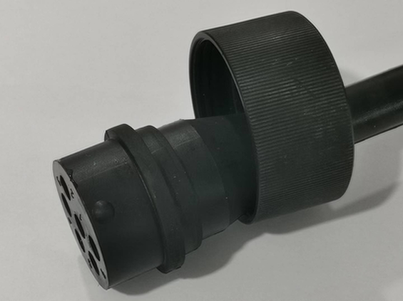
HYSF SUBSEA IEB4F 4-Channel Female EO Underwater Pluggable Connector is a multi-channel wet-mate fiber optic connector designed for ROV systems, AUV platforms, subsea cameras, oceanographic instruments, and underwater communication networks.Featuring four independent optical fiber channels within one compact connector interface, the IEB4F provides a high-bandwidth optical connection solution for demanding subsea applications.The connector supports both single-mode (SM) and multimode (MM) fiber configurations, providing flexibility for different underwater communication systems.Its wet-mate design allows compatible male and female connector halves to be connected and disconnected underwater when operated within the specified environmental and installation conditions.The reference product configuration features a chloroprene rubber connector body, a 316 stainless steel housing, precision zirconia optical ferrules, and protective wiper rings.Titanium housing is available as an optional material for weight-sensitive subsea equipment.The published reference specifications identify optical insertion loss below 0.5 dB per channel and return loss above 40 dB.For single-mode fiber configurations, the reference data rate is up to 10 Gbps, while multimode configurations support up to 1 Gbps.The IEB4F is particularly suitable for underwater systems requiring multiple optical communication channels within a compact wet-mate connector.
Key Features and Benefits
1. Four-Channel Fiber Optic Configuration
The IEB4F incorporates four independent optical fiber channels within one underwater connector interface.This multi-channel configuration allows engineers to integrate multiple optical communication paths into a single compact connection.Typical applications include:
- ROV fiber optic tether connections
- Subsea camera systems
- High-resolution underwater video transmission
- Sonar data communication
- AUV communication systems
- Oceanographic instrumentation
- Subsea sensor networks
- Offshore monitoring systems
The four-channel design helps reduce the number of individual optical connectors required in multi-channel underwater equipment.
2. Wet-Mate Underwater Connection
The IEB4F features a wet-mate optical connection design.Compatible connector halves can be connected and disconnected underwater, making it suitable for subsea installations where equipment recovery is difficult or expensive.The reference design uses protective chloroprene wiper rings around the optical mating interface.These components help protect the optical mating surfaces during underwater connection.Key benefits include:
- Underwater connection capability
- Underwater disconnection capability
- Reduced equipment recovery requirements
- Convenient ROV-assisted intervention
- Flexible subsea equipment replacement
- Suitable for permanent underwater installations
The approved mating procedure must be followed to protect the optical surfaces and sealing components.
3. Single-Mode and Multimode Fiber Compatibility
The IEB4F supports different optical fiber configurations.
Single-Mode Fiber (SM)- Fiber specification: 9/125 μm
- Reference data rate: Up to 10 Gbps
- Suitable for long-distance optical communication
- Suitable for high-bandwidth subsea networks
- Suitable for ROV video and sonar data transmission
Multimode Fiber (MM)- Fiber specification: 50/125 μm
- Fiber specification: 62.5/125 μm
- Reference data rate: Up to 1 Gbps
- Suitable for compatible shorter-distance optical links
- Suitable for selected underwater instrumentation systems
The appropriate fiber type should be selected according to transmission distance, optical equipment compatibility, wavelength, and network requirements.
4. Low Optical Insertion Loss
The published IEB4F reference specification identifies typical optical insertion loss below 0.5 dB per channel.Low insertion loss helps minimize optical signal attenuation at the connector interface.This is particularly important for applications involving:
- High-definition underwater video
- ROV fiber optic communication
- Subsea Ethernet networks
- Sonar data transmission
- Oceanographic measurement systems
- Long-distance optical communication
Actual optical performance depends on fiber type, optical alignment, end-face condition, mating procedure, and operating environment.
5. High Optical Return Loss
The reference product specification lists optical return loss greater than 40 dB.High return loss helps minimize reflected optical power at the connector interface.This is beneficial for optical communication systems requiring stable transmission performance and reliable signal quality.Actual return loss should be verified using the specified fiber type and test wavelength.
6. Precision Zirconia Optical Ferrules
The reference IEB4F design uses precision zirconia optical ferrules.Zirconia ceramic provides a stable optical alignment structure and good wear resistance.The precision ferrule arrangement helps maintain repeatable optical performance during repeated connector mating operations.Proper cleaning and inspection of the optical mating surfaces remain essential for maintaining low insertion loss.
7. Chloroprene Rubber Connector Body
The IEB4F reference configuration features a chloroprene rubber connector body.The elastomer construction provides mechanical protection around the optical interface and supports the underwater sealing arrangement.Its flexible construction helps protect the internal optical components during subsea operation.Key characteristics include:
- Flexible elastomer construction
- Environmental sealing
- Mechanical protection
- Resistance to marine exposure
- Suitable for subsea applications
8. Corrosion-Resistant Stainless Steel Housing
The reference IEB4F configuration uses 316 stainless steel for its housing.This material provides mechanical strength and corrosion resistance for marine and subsea applications.Titanium is available as an optional housing material.Potential material options include:
- 316 Stainless Steel
- Titanium (Optional)
Titanium can be considered for weight-sensitive ROV and AUV equipment.The final material selection should consider operating depth, seawater exposure, mechanical loading, and equipment weight requirements.
9. Protective Optical Sealing System
The IEB4F reference design incorporates chloroprene wiper rings and nitrile O-ring seals.These components help protect the optical mating interface during subsea operation.The wiper rings help reduce contamination around the optical mating surfaces during connection and disconnection.The O-ring sealing arrangement supports the connector’s environmental sealing requirements.All sealing components should be inspected before deployment.
10. Secure Locking Mechanism
The reference IEB4F configuration provides POM or stainless steel locking sleeve options.The locking sleeve helps secure the connector after mating and reduces the risk of accidental separation.The appropriate locking sleeve must be installed according to the approved connector configuration.The connector should not be deployed with a required locking component missing.
11. Four-Channel High-Speed Optical Communication
The IEB4F is designed for multi-channel underwater optical data transmission.The reference product specification identifies:
- Four independent optical channels
- Up to 10 Gbps for single-mode fiber
- Up to 1 Gbps for multimode fiber
- Optical insertion loss below 0.5 dB per channel
- Optical return loss above 40 dB
These capabilities make the connector suitable for multi-channel underwater communication systems.Potential applications include high-resolution subsea video, sonar data uplinks, underwater sensor networks, and ROV optical communication.The actual system transmission rate depends on the complete optical link, including transceivers, fiber construction, cable length, and network equipment.
12. 300 Bar Mated Pressure Rating
The published IEB4F reference specification lists a mated pressure rating of 300 bar (4,350 psi).This corresponds to approximately 3,000 meters of seawater pressure depth in pressure-equivalent terms.The connector is therefore intended for demanding ROV, AUV, and subsea instrumentation applications within its qualified pressure envelope.The reference product page does not specify an open-face pressure rating.The pressure rating of the complete installation must be confirmed through the approved hydrostatic qualification procedure.
13. Flexible Subsea Cable Options
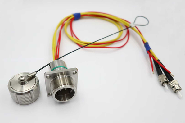
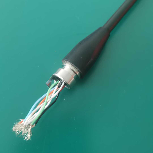
The IEB4F can be integrated into customized underwater fiber optic cable assemblies.The reference product information identifies the following cable jacket options:
- Polyurethane (PUR)
- Synthetic Rubber
Cable length, outer diameter, fiber construction, and termination requirements can be specified according to the intended application.The complete cable assembly should be designed to meet the mechanical and environmental requirements of the subsea system.
14. Customization for OEM Projects
HYSF SUBSEA can evaluate customized configurations for subsea equipment manufacturers and system integrators.Potential customization requirements include:
- Single-mode or multimode fiber
- Four-channel optical configuration
- Cable length
- Cable jacket material
- Cable outer diameter
- Stainless steel housing
- Titanium housing
- Locking sleeve material
- Optical fiber termination
- Optical insertion loss testing
- Optical return loss testing
- Hydrostatic pressure testing
- Customized optical cable assemblies
Customized configurations should be reviewed and approved against the final mechanical and optical specifications before production.
IEB4F Technical Specifications
| Parameter | Reference Specification |
|---|
| Brand | HYSF SUBSEA |
| Model | IEB4F |
| Connector Series | IE-Series EO |
| Product Type | Female EO Underwater Pluggable Connector |
| Connector Gender | Female |
| Optical Channels | 4 |
| Fiber Type | Single-Mode / Multimode |
| SM Fiber | 9/125 μm |
| MM Fiber | 50/125 μm / 62.5/125 μm |
| Optical Insertion Loss | <0.5 dB / Channel |
| Optical Return Loss | >40 dB |
| Data Rate (SM) | Up to 10 Gbps |
| Data Rate (MM) | Up to 1 Gbps |
| Electrical Voltage | N/A – Optical Only |
| Electrical Current | N/A – Optical Only |
| Mated Pressure Rating | 300 bar / 4,350 psi |
| Open-Face Pressure | Not Specified |
| Water Temperature | −4°C to +60°C |
| Air Temperature | −40°C to +60°C |
| Connector Body | Chloroprene Rubber |
| Housing Material | 316 Stainless Steel |
| Optional Housing | Titanium |
| Optical Ferrule | Zirconia |
| Sealing | Chloroprene Wiper Rings / Nitrile O-Rings |
| Locking Sleeve | POM / Stainless Steel |
| Cable Jacket | PUR / Synthetic Rubber |
| Cable Length | Customized |
Engineering Note: These specifications are based on the publicly available IEB4F product description. The source contains inconsistencies regarding product configuration and wet-mate cycle life. The 300 bar mated pressure rating should be treated as a reference value until confirmed by the approved product drawing and hydrostatic test report.
Optical Fiber Configuration
The IEB4F provides four optical channels for subsea data transmission.The reference fiber configurations include:
| Fiber Type | Core / Cladding | Reference Data Rate | Typical Application |
|---|
| Single-Mode | 9/125 μm | Up to 10 Gbps | Long-distance optical communication |
| Multimode | 50/125 μm | Up to 1 Gbps | Compatible shorter-distance links |
| Multimode | 62.5/125 μm | Up to 1 Gbps | Compatible instrumentation links |
The optical fiber configuration should be selected according to the customer’s network architecture and optical equipment.Before production, verify:
- Fiber type.
- Optical wavelength.
- Four-channel fiber assignment.
- Optical connector polarity.
- Optical insertion loss.
- Optical return loss.
- Cable length.
- Optical test requirements.
All four optical channels should be tested individually before final assembly acceptance.
Compatible Connectors and Accessories
IEB4M – 4-Channel Male EO Connector
The IEB4M is the corresponding male connector within the four-channel EO underwater connector family.It is designed to mate with the compatible IEB4F female connector.Both configurations provide a four-channel optical connection interface.
Protective Dummy Plugs
Protective dummy plugs can be specified to protect the optical mating interface when the operational mating connector is not installed.The appropriate dummy configuration should be confirmed according to the connector design.
Locking Sleeves
POM and stainless steel locking sleeve options are identified in the reference product information.The correct locking sleeve should be selected according to the final mating configuration.
Protective Caps
Protective caps can be used to protect the optical interface during storage, transportation, and equipment handling.Always verify accessory compatibility before ordering.
Typical Applications of IEB4F
1. ROV Fiber Optic Tether Connections
The IEB4F can be used in ROV fiber optic tether systems requiring multiple high-bandwidth optical communication channels.It is suitable for transmitting video, sonar, and control data between underwater equipment and surface systems.
2. Subsea Camera Systems
Underwater camera systems frequently require high-bandwidth optical communication for transmitting high-resolution video and image data.The four-channel configuration provides a compact optical interface for multi-channel camera installations.
3. AUV Docking Systems
Autonomous underwater vehicles may require optical connections for communication and data transfer during subsea docking operations.The wet-mate design provides flexibility for underwater docking interfaces.
4. USBL and Acoustic Positioning Systems
Underwater positioning systems may incorporate optical communication interfaces between sensors, transponders, and subsea processing equipment.
5. Oceanographic CTD and ADCP Equipment
Oceanographic instruments such as CTD profilers and ADCP systems may require optical communication interfaces for transferring measurement data.
6. Subsea Sensor Networks
Underwater monitoring networks require reliable data transmission between distributed sensors and subsea communication nodes.Fiber optic connections provide high bandwidth and immunity to electromagnetic interference.
7. Offshore Wind Foundation Monitoring
Offshore wind monitoring systems may incorporate optical communication links between underwater sensors and subsea monitoring equipment.
8. Subsea Observatories
Permanent underwater observatories require reliable communication connections between sensors, monitoring nodes, and subsea data distribution systems.
9. Offshore Oil and Gas Monitoring
Subsea oil and gas systems use optical communication networks for equipment monitoring, instrumentation, and remote data transmission.
10. Marine Research Equipment
Oceanographic research platforms frequently use optical connections for transmitting scientific measurement data and high-resolution imaging.
Installation and Maintenance Guidelines
Step 1: Inspect the Optical Connector
Inspect both connector halves for visible damage, contamination, or defects.Check the optical interface and protective sealing components.
Step 2: Inspect the Sealing Components
Check the wiper rings and O-rings for cuts, deformation, or contamination.Replace damaged sealing components according to the approved maintenance procedure.
Step 3: Check Optical Fiber Compatibility
Confirm that both connector halves use compatible fiber types and optical configurations.Verify single-mode or multimode compatibility.
Step 4: Clean the Optical Interface
Use approved optical cleaning materials and procedures.Avoid touching the optical ferrule surfaces directly.
Step 5: Align the Connector Halves
Align the mechanical guide features and optical mating interface before connection.Avoid forcing the connectors together at an angle.
Step 6: Complete the Wet-Mate Connection
Follow the manufacturer’s underwater mating procedure.Ensure that the connector is fully engaged and that the locking mechanism is correctly installed.
Step 7: Verify the Locking Sleeve
Install the specified POM or stainless steel locking sleeve before deployment.Check that the connector cannot become accidentally disengaged.
Step 8: Perform Optical Testing
Verify optical insertion loss and return loss according to the approved testing procedure.Test all four optical channels individually.
Step 9: Complete Pressure Qualification
Verify the complete connector and cable assembly against the required hydrostatic pressure rating.
Step 10: Post-Deployment Maintenance
Inspect the connector after recovery.Clean the mating surfaces and install protective caps when the connector is not in use.
Important: Wet-mate connectors must be operated according to the manufacturer’s specified mating and environmental conditions. Never force a connection or exceed the qualified operating pressure.
Quality Control and Testing
Depending on the approved product configuration and project requirements, HYSF SUBSEA quality-control procedures may include:
- Visual inspection
- Dimensional verification
- Optical ferrule inspection
- Fiber identification
- Optical continuity testing
- Four-channel optical verification
- Optical insertion loss measurement
- Optical return loss measurement
- Mating compatibility testing
- Locking sleeve inspection
- Sealing component inspection
- Hydrostatic pressure testing
- Optical performance verification after pressure testing
Optical test reports and hydrostatic pressure test certificates can be specified according to the agreed project requirements.
Frequently Asked Questions
Q1: What is the IEB4F underwater connector?
The IEB4F is a four-channel female EO underwater pluggable connector designed for subsea fiber optic communication.
Q2: How many optical channels does the IEB4F have?
It features four independent optical channels.
Q3: Is the IEB4F wet-mate or dry-mate?
The published product description specifies a wet-mate underwater optical connector.It is designed to connect and disconnect underwater with its compatible mating connector.
Q4: What is the difference between IEB4F and IEB4M?
IEB4F is the female connector, while IEB4M is the corresponding male connector.Both feature four optical channels.
Q5: Which fiber types are supported?
The reference configuration supports single-mode 9/125 μm and multimode 50/125 μm or 62.5/125 μm fibers.
Q6: What is the optical insertion loss?
The reference product specification lists typical insertion loss below 0.5 dB per channel.
Q7: What is the optical return loss?
The reference specification lists return loss greater than 40 dB.
Q8: What is the maximum data transmission rate?
The reference product specification lists up to 10 Gbps for single-mode fiber and up to 1 Gbps for multimode fiber.
Q9: What is the pressure rating?
The published detailed specification lists 300 bar (4,350 psi) when mated.The open-face pressure rating is not specified.
Q10: Is the IEB4F suitable for 7,000-meter underwater operation?
The detailed product specification lists 300 bar, which is approximately equivalent to 3,000 meters of seawater pressure depth.A 7,000-meter rating should not be claimed without separate engineering qualification.
Q11: What materials are available?
The reference configuration uses a chloroprene rubber body and 316 stainless steel housing, with titanium available as an option.
Q12: Does the IEB4F transmit electrical power?
The referenced IEB4F configuration is specified as optical only, with four optical channels.It does not have a specified electrical voltage or current rating.
Q13: Can the cable length be customized?
Cable length and cable jacket requirements can be specified according to the intended installation and approved product configuration.
Q14: Are protective accessories available?
Compatible locking sleeves, dummy plugs, and protective caps can be specified according to the connector configuration.
Q15: Can optical test reports be supplied?
Optical insertion loss and return loss testing can be specified according to the agreed quality-control requirements.
Why Choose HYSF SUBSEA IEB4F?
The
HYSF SUBSEA IEB4F 4-Channel Female EO Underwater Pluggable Connector provides a multi-channel optical connection solution for demanding subsea communication systems.Its principal features include:
- Four-channel optical configuration
- Female underwater connector
- Wet-mate connection capability
- Single-mode and multimode fiber compatibility
- Optical insertion loss below 0.5 dB per channel (Reference)
- Optical return loss above 40 dB (Reference)
- Single-mode transmission up to 10 Gbps (Reference)
- Multimode transmission up to 1 Gbps (Reference)
- Precision zirconia optical ferrules
- 316 stainless steel housing
- Optional titanium housing
- Chloroprene rubber connector body
- Protective optical wiper rings
- POM or stainless steel locking sleeve
- PUR or synthetic rubber cable options
- Customized optical cable assemblies
- Optical testing and hydrostatic qualification options
For ROV manufacturers, AUV developers, subsea communication integrators, oceanographic research organizations, and offshore engineering companies, the IEB4F offers a compact four-channel optical interface for underwater communication systems.