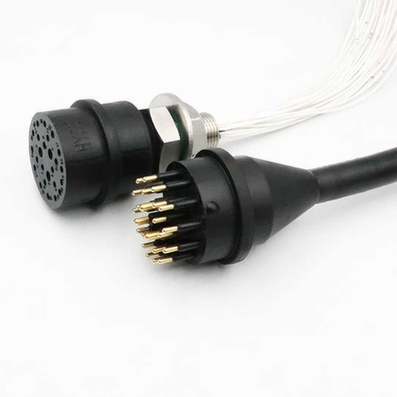
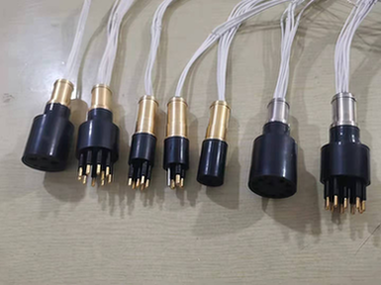
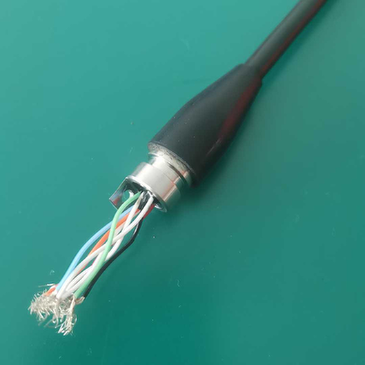
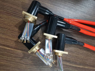
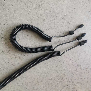
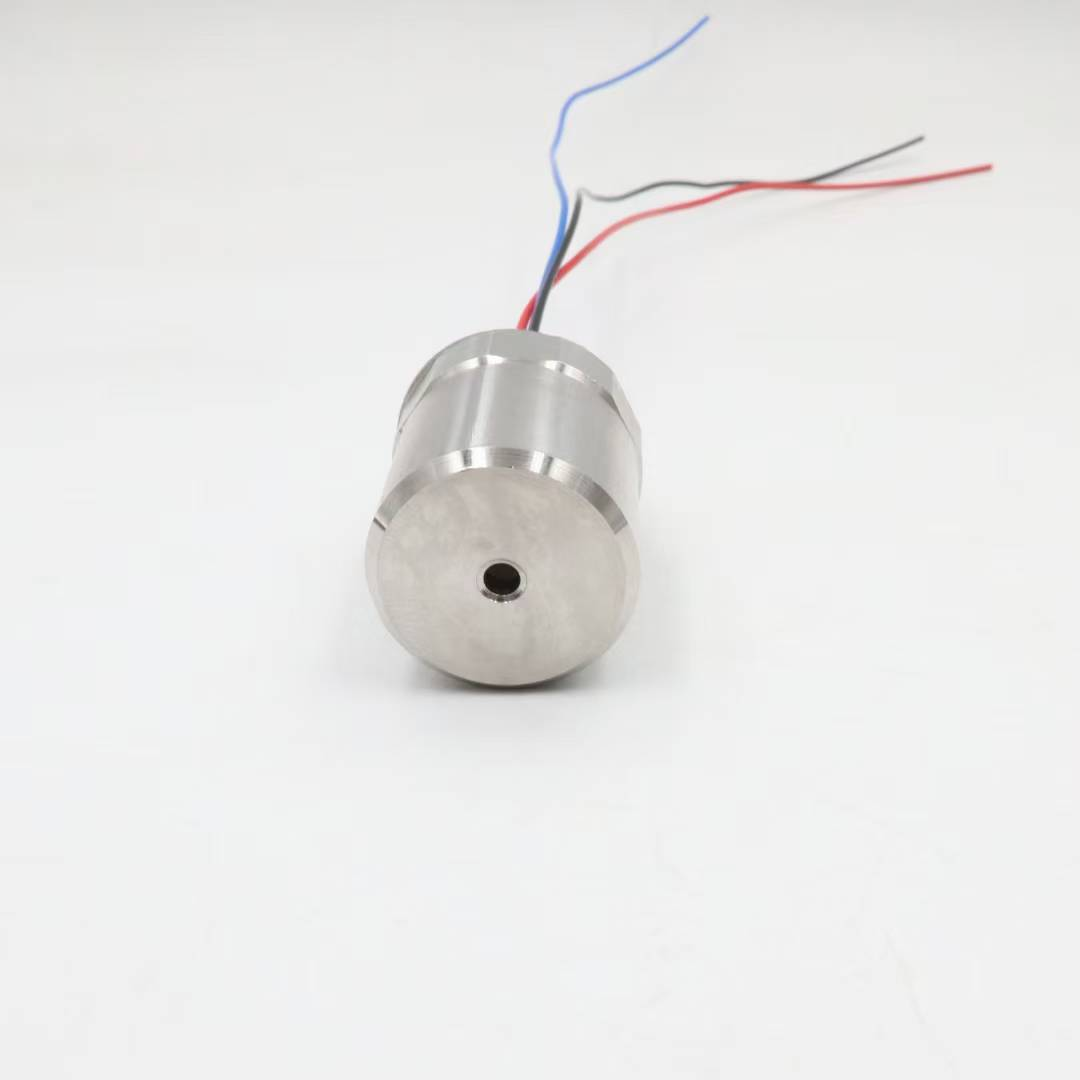
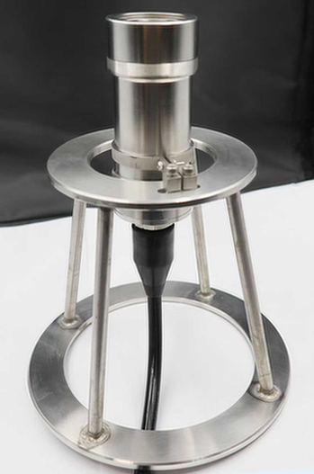
5506-2013 Burton 55 Series Compatible 13-Pin Flange Mount Receptacle Underwater Connector
Product Overview
The
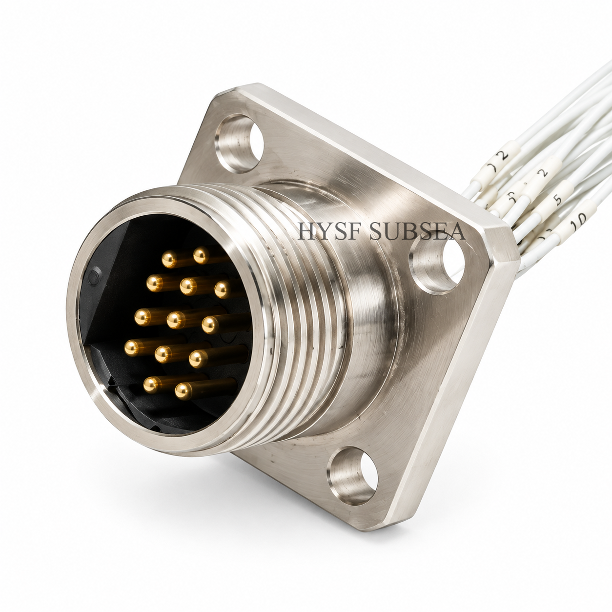
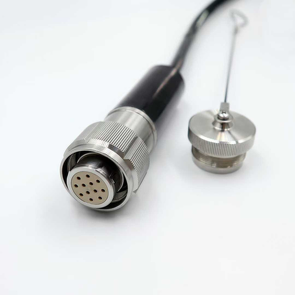
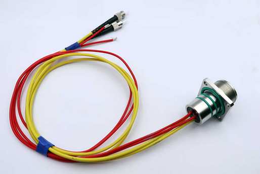
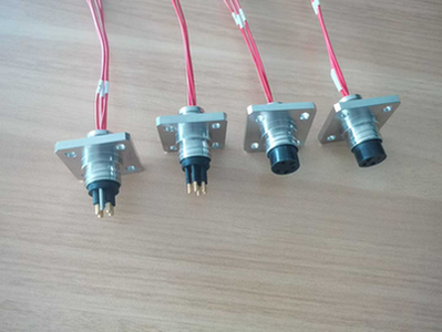
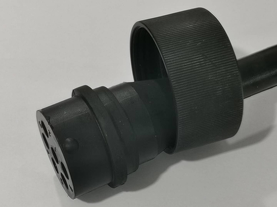
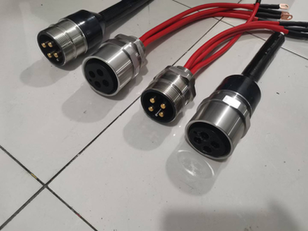
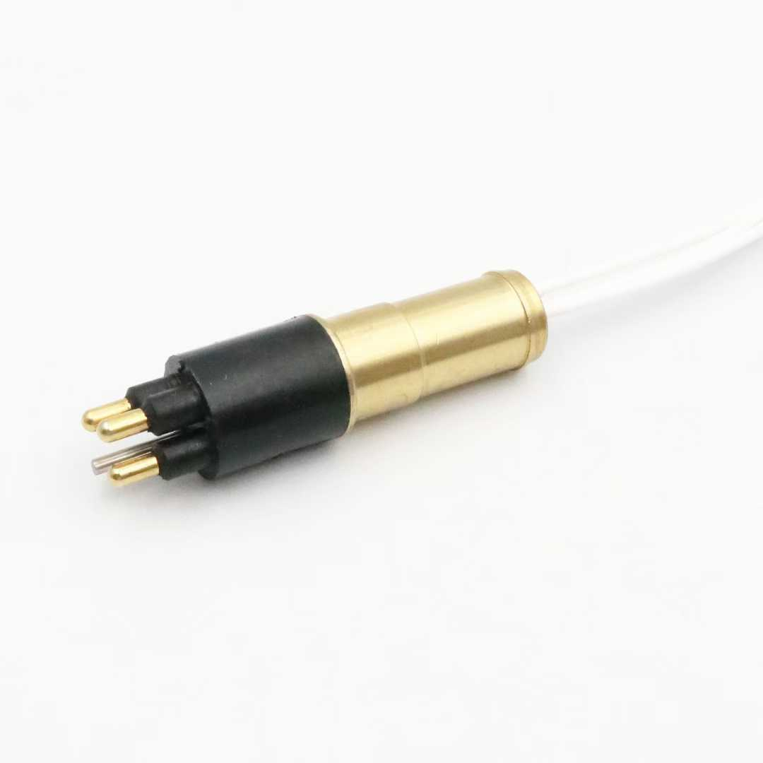
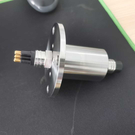
HYSF SUBSEA 5506-2013 Burton 55 Series Compatible 13-Pin Flange Mount Receptacle is a subsea electrical connector designed for underwater equipment, ROV systems, and offshore installations requiring a reliable multi-contact electrical interface.Featuring a Shell Size 20 configuration and thirteen male pin contacts, the 5506-2013 provides a high-density electrical connection for compatible Burton 5500 Series cable plugs.The connector follows the Burton 55 Series mating interface and features a flange-mounted receptacle design for installation on equipment panels, subsea housings, and electrical enclosures.The original Burton contact arrangement specifies thirteen 18 AWG conductors for the 2013 configuration.Its construction features a passivated 316L stainless steel shell, an integrally molded elastomer body, and high-conductivity copper-alloy electrical contacts.The flange mounting design provides a fixed electrical interface for equipment installations. Rear pigtail connections allow the receptacle to be integrated into customer electrical systems and internal wiring assemblies.A dedicated Ethernet and power configuration is also available within the Burton 5500 Series, supporting 1000Base-T network performance with the appropriate cable and wiring arrangement.The 5506-2013 is suitable for ROV systems, subsea control modules, underwater instrumentation, electrical distribution equipment, marine research systems, and offshore installations.
Key Features and Benefits
1. Thirteen-Pin Electrical Configuration
The 5506-2013 features thirteen male pin contacts in a Shell Size 20 configuration.The thirteen-contact arrangement provides multiple independent electrical circuits within a single subsea connector interface.Typical applications include:
- Multi-channel power connections
- ROV electrical systems
- Subsea control circuits
- Underwater sensor connections
- Marine instrumentation
- Auxiliary equipment connections
- Subsea monitoring systems
- Multi-conductor cable assemblies
- Combined power and signal distribution
The thirteen male pin contacts are designed to mate with compatible female socket contacts in the Burton 55 Series cable plugs.
2. Burton 55 Series Compatibility
The 5506-2013 follows the Burton 5500 Series dimensional and mating interface.The 55 Series is widely used in subsea equipment, ROV systems, offshore installations, and underwater electrical assemblies.Its standardized interface allows compatible cable plugs and receptacles to be integrated into existing subsea systems.The 5506-2013 can be considered as a replacement or alternative for compatible Burton 55 Series flange receptacles.Compatibility should be confirmed against the exact shell size, contact arrangement, keyway, and mating dimensions.
3. Shell Size 20 Configuration
The 5506-2013 uses a Shell Size 20 metal shell with thirteen electrical contacts.The Shell Size 20 configuration provides sufficient space for thirteen independent electrical contact positions within a single connector interface.It is particularly suitable for subsea equipment requiring multiple power, control, signal, and communication circuits.
4. Thirteen 18 AWG Conductors
The original Burton technical catalog specifies the 2013 contact arrangement as:
13 × 18 AWG conductorsThis configuration provides thirteen independent electrical contact positions within the Shell Size 20 connector body.It is suitable for appropriately designed power, control, instrumentation, and signal circuits.Actual current capacity must be determined according to conductor size, cable construction, operating temperature, conductor bundling, and electrical loading.The 18 AWG conductor specification should not be interpreted as a fixed current rating for every contact.
5. Flange Mount Installation Design
The 5506-2013 is a Flange Connector Receptacle (FCR).Unlike inline cable plugs and threaded bulkhead receptacles, the FCR configuration is designed for direct flange or panel mounting.Its mounting structure allows the connector to be securely installed on equipment housings and subsea electrical enclosures.The original Burton installation documentation specifies a four-bolt mounting arrangement.For Shell Size 20, the recommended mounting configuration is:
- Four mounting bolts
- Recommended bolt size: 1/4 inch
- Recommended mounting torque: 45 lb-in
The mounting arrangement also requires a central panel opening.The flange design is particularly useful for applications requiring a fixed electrical interface on an equipment panel.
6. Thirteen Male Pin Contacts
The 5506-2013 features thirteen male pin contacts.In the Burton 5500 Series connector architecture, receptacles contain male pin contacts, while cable plugs contain female socket contacts.This arrangement is designed to prevent exposed powered pins on the cable plug side during normal power transmission.The original Burton catalog specifies high-conductivity copper-alloy electrical contacts.
7. Integrally Molded Elastomer Body
The connector features an integrally molded elastomer body.The molding process bonds the elastomer to the internal metal structure, providing mechanical protection and environmental sealing.The molded construction helps protect the electrical contacts and internal termination area.The original Burton design incorporates face-type sealing technology to support reliable subsea operation.
8. Passivated 316L Stainless Steel Shell
The standard Burton 5500 Series uses passivated 316L stainless steel for its connector shells.This material provides:
- Marine corrosion resistance
- Mechanical strength
- Seawater compatibility
- Structural protection
- Long-term subsea equipment suitability
The stainless steel shell provides a robust mechanical interface for demanding offshore and underwater applications.
9. 600V Standard Voltage Rating
The standard Burton 5500 Series voltage rating is 600 V.This makes the connector suitable for appropriately designed subsea power and control circuits.The original Burton high-voltage catalog also lists the 2013 contact arrangement as available in a selected 1000 V configuration.Higher-voltage versions require specific contact shoulders and insulation materials.The standard 5506-2013 configuration should not be assumed to support 1000 V without confirmation of the special high-voltage configuration.
10. High-Pressure Subsea Capability
The Burton 5500 Series technical documentation specifies an operating pressure rating of 10,000 psi, approximately 690 bar.The connector family uses rugged metal shells, recessed receptacle pins, and integrated face-type sealing technology.This construction is designed for demanding underwater applications.The complete installed assembly should be evaluated according to the mating plug, mounting configuration, sealing surfaces, and operating environment.
11. Rear Pigtail Electrical Connections
The 5506-2013 flange receptacle is designed for panel-mounted installation with rear electrical connections.The original Burton catalog specifies MIL-W-16878 for pigtail wiring.The pigtails allow the receptacle to be integrated into customer equipment and internal electrical systems.Available customization options may include:
- Pigtail length
- Conductor identification
- Wire termination
- Cable specification
- Customized wiring arrangement
- Special installation requirements
The exact pigtail length and termination should be specified according to the final ordering configuration.
12. Ethernet and Power Combination
A dedicated Ethernet and power configuration is available for the Burton 5500 Series 13-pin connector arrangement.The Ethernet solution allows subsea equipment to receive electrical power and network communication through a single connector and cable assembly.The original Burton technical catalog specifies:
- 1000Base-T Ethernet
- Up to 1 Gbps network performance
- Combined Ethernet and power transmission
- 600 V voltage rating
- 10,000 psi pressure rating
- Cable lengths up to 75 meters
The corresponding Ethernet configuration is identified by the special part-number designation:
5506-2013-EXXXThis configuration is particularly useful for subsea cameras, ROV communication systems, underwater network devices, and subsea monitoring equipment.Important: Gigabit Ethernet performance requires the appropriate Ethernet-specific cable construction, contact assignment, and wiring configuration. A standard 13-pin receptacle does not automatically provide Ethernet functionality.
13. Dry-Mate Connection Design
The Burton 5500 Series is a dry-mate underwater connector family.Its mating interface uses an integrated face-type sealing arrangement.The connector should be connected and disconnected in a dry environment, with electrical circuits de-energized before mating or unmating.It should not be treated as a connector designed for live underwater mating operations.
14. Suitable for ROV and Offshore Applications
The 5506-2013 is particularly suitable for underwater equipment requiring a fixed thirteen-contact electrical interface.Potential applications include:
- Work-Class ROV systems
- ROV toolskids
- Subsea electrical enclosures
- Subsea control modules
- Underwater instrumentation
- Offshore inspection equipment
- Marine research systems
- Subsea monitoring equipment
- AUV and underwater robotic systems
- Subsea Ethernet communication
- Subsea electrical distribution
5506-2013 Technical Specifications
| Parameter | Specification |
|---|
| Brand | HYSF SUBSEA |
| Model | 5506-2013 |
| Connector Series | Burton 5500 Series Compatible |
| Product Type | Flange Connector Receptacle (FCR) |
| Installation Type | Flange Mount / Panel Mount |
| Shell Size | 20 |
| Number of Contacts | 13 |
| Contact Gender | Male Pin |
| Contact Arrangement | 13 × 18 AWG |
| Connector Configuration | Fixed Receptacle |
| Mounting Method | Four-Bolt Flange |
| Mounting Bolt Size | 1/4 inch |
| Recommended Bolt Torque | 45 lb-in |
| Rear Termination | Pigtail Leads |
| Pigtail Specification | MIL-W-16878 |
| Pigtail Length | Customized / Order-Specified |
| Shell Material | Passivated 316L Stainless Steel |
| Connector Body Material | Integrally Molded Elastomer |
| Contact Material | High-Conductivity Copper Alloy |
| Standard Voltage Rating | 600 V |
| Optional High-Voltage Configuration | 1000 V |
| Current Capacity | Refer to Ampacity Appendix and approved configuration |
| Pressure Rating | 10,000 psi / Approximately 690 bar |
| Ethernet Configuration | 1000Base-T + Power, dedicated assembly |
| Ethernet Performance | Up to 1 Gbps |
| Ethernet Cable Length | Up to 75 m (original Burton catalog specification) |
| Connector Type | Dry-Mate |
| Mating Connector | 5501-2013 Cable Plug |
Engineering Note: The original Cooper Interconnect Burton 5500 Series technical catalog specifies the 2013 contact arrangement as thirteen 18 AWG conductors. It specifies a standard 600 V rating, 10,000 psi pressure rating, passivated 316L stainless steel shells, integrally molded elastomer bodies, and high-conductivity copper-alloy contacts.The original catalog directs users to its Ampacity appendix for current capacity rather than specifying a universal current rating for the 2013 arrangement.The exact electrical ratings, contact plating, cable specifications, dimensions, and pressure qualification of the HYSF production version should be confirmed against approved engineering drawings and test records.
Thirteen-Pin Contact Configuration
The 5506-2013 features thirteen male pin contacts.The original Burton contact arrangement identifies the 2013 configuration as:
13 × 18 AWGThe Burton 5500 Series uses male pin contacts in receptacles and female socket contacts in cable plugs.The thirteen-contact arrangement provides an electrical interface for appropriately designed power, signal, control, and instrumentation circuits.Before cable assembly or equipment integration, engineers should verify:
- The thirteen contact positions.
- The mating-face orientation.
- The conductor identification.
- The pin-to-wire assignment.
- Ethernet differential pair assignments, where applicable.
- Electrical continuity.
- Insulation resistance.
- Rear pigtail termination requirements.
For Ethernet applications, the correct differential-pair assignment and cable construction are particularly important for maintaining signal integrity.
Important: The exact contact numbering and conductor colors should follow the approved 5506-2013 production wiring diagram.
Flange Mounting Configuration
The 5506-2013 is designed for fixed installation on an equipment panel or flange.Its four-bolt mounting arrangement provides a secure mechanical connection between the receptacle and equipment housing.According to the original Burton installation documentation, the Shell Size 20 mounting configuration uses:
| Mounting Parameter | Specification |
|---|
| Mounting Style | Four-Bolt Flange |
| Panel Opening | Central Connector Opening |
| Bolt Size | 1/4 inch |
| Recommended Bolt Torque | 45 lb-in |
| Connector Type | FCR |
| Installation | Panel / Equipment Housing |
The panel cutout, bolt-hole spacing, sealing interface, and installation depth should be confirmed against the approved mechanical drawing before manufacturing the mounting panel.The Burton FCR construction is machined from a larger stainless steel block and uses a five-hole panel installation arrangement: one central connector opening and four mounting bolt holes.An additional O-ring on the flange surface can also be requested as a special configuration.
Compatible Connectors and Accessories
5501-2013 – 13-Pin Straight Cable Plug
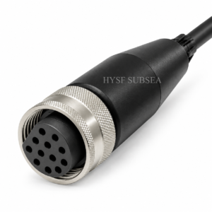
The Burton 5501-2013 is a straight cable connector plug with thirteen female socket contacts.It is the corresponding cable-mounted mating connector for the 5506-2013 flange receptacle.The two connectors provide a compatible thirteen-contact electrical interface for subsea cable assemblies.
5507-2013 – 13-Pin Bulkhead Receptacle
The Burton 5507-2013 is a bulkhead connector receptacle configuration.It provides an alternative installation arrangement for equipment requiring a threaded bulkhead-mounted electrical connection rather than a four-bolt flange installation.
5502-2013 – 13-Pin Cable Receptacle
The Burton 5502 Series is an inline cable-mounted receptacle configuration.It can be considered for specialized cable splice assemblies and cable-to-cable electrical connections.
Burton 55 Series Dummy Plug
A compatible dummy plug can be used to protect connector interfaces when the operational cable plug is not installed.The dummy plug should be selected according to the corresponding shell size and interface configuration.
5506-2013-EXXX – Ethernet and Power Flange Receptacle
This is the dedicated Ethernet and power configuration of the 13-pin flange receptacle.It can be considered for subsea equipment requiring both electrical power and 1000Base-T network communication through one connector interface.
Note: Verify the exact ordering configuration, contact arrangement, keyway, mounting dimensions, and Ethernet wiring requirements before ordering mating connectors and accessories.
Typical Applications of 5506-2013
1. Remotely Operated Vehicles (ROVs)
The 5506-2013 provides a fixed thirteen-contact electrical interface for ROV electrical systems, tooling, auxiliary equipment, and subsea instrumentation.
2. Subsea Ethernet Communication
The dedicated Ethernet and power configuration can be used for connecting subsea cameras, network devices, and communication equipment.
3. Subsea Electrical Enclosures
Subsea electrical enclosures require reliable panel-mounted connectors for connecting internal electrical circuits to external equipment.The flange mounting configuration provides a practical installation solution.
4. Subsea Control Modules
Subsea control systems may incorporate multiple electrical connections for monitoring, instrumentation, and auxiliary functions.The thirteen-contact configuration can be considered for systems requiring multiple independent electrical circuits.
5. Marine Instrumentation
Marine sensors and instrumentation systems require reliable electrical connections for power, signal transmission, and monitoring.The 5506-2013 offers a fixed panel-mounted interface for suitable applications.
6. Offshore Inspection Equipment
Offshore inspection systems frequently use subsea cameras, sensors, lighting equipment, and electrical tools.The connector can be integrated into compatible underwater equipment housings.
7. AUV and Underwater Robotic Systems
Autonomous underwater vehicles and robotic platforms frequently require multiple electrical interfaces for sensors, control systems, and auxiliary equipment.The 5506-2013 provides thirteen contact positions for appropriately designed electrical connections.
8. Subsea Monitoring Networks
Subsea monitoring systems require reliable connections for network communication, sensor signals, and auxiliary power.The dedicated Ethernet and power configuration provides a practical connection option for compatible systems.
9. Oceanographic Research Equipment
Underwater research equipment often requires multiple electrical circuits for sensors, monitoring devices, and auxiliary systems.The flange-mounted configuration provides a practical connection option for compatible research equipment.
Installation and Maintenance Guidelines
Step 1: Inspect the Connector
Inspect the connector shell, male contacts, molded body, flange surface, and rear pigtails for visible damage.
Step 2: Verify Compatibility
Confirm the Shell Size 20 configuration, thirteen-contact arrangement, keyway, and mating interface of the cable plug.
Step 3: Prepare the Mounting Panel
Verify the central panel opening, four mounting holes, installation depth, and sealing surface against the approved mechanical drawing.
Step 4: Install the Receptacle
Position the connector correctly and secure it using the specified four mounting bolts.Follow the recommended mounting torque for the approved configuration.
Step 5: Connect the Rear Pigtails
Connect the thirteen pigtail conductors according to the approved wiring diagram.
Step 6: Verify Electrical Continuity
Check all thirteen conductors and verify the approved wiring assignments.
Step 7: Verify Ethernet Wiring
For Ethernet configurations, verify the differential pairs, cable construction, and applicable transmission requirements.
Step 8: Mate the Connector
Follow the manufacturer’s recommended mating procedure and ensure correct mechanical alignment with the compatible cable plug.
Step 9: Perform System Testing
Verify electrical continuity, insulation resistance, mounting integrity, and the complete assembly’s pressure qualification before deployment.
Step 10: Maintain After Use
Inspect the connector after recovery and follow the manufacturer’s recommended cleaning and maintenance procedures.
Important: The Burton 5500 Series is a dry-mate connector family. Circuits should be de-energized before mating or unmating. Do not treat this connector as a wet-mate connector.
Quality Control and Testing
Depending on the ordered configuration and project requirements, HYSF SUBSEA quality-control procedures may include:
- Visual inspection
- Dimensional verification
- Flange mounting inspection
- Contact inspection
- Electrical continuity testing
- Insulation resistance measurement
- Contact resistance measurement
- Pigtail identification checks
- Ethernet continuity and performance testing
- Mating compatibility verification
- Mechanical inspection
- Hydrostatic pressure testing
The applicable test procedures and acceptance criteria should be established according to the approved connector configuration and intended operating environment.
Frequently Asked Questions
Q1: What is the 5506-2013 underwater connector?
The 5506-2013 is a thirteen-pin flange-mounted receptacle from the Burton 5500 Series, featuring Shell Size 20 and male pin contacts.
Q2: How many contacts does the 5506-2013 have?
It features thirteen male pin contacts.
Q3: Is the 5506-2013 a male or female connector?
The 5506-2013 receptacle uses male pin contacts. Its compatible cable plug uses female socket contacts.
Q4: What is the shell size?
The connector uses Shell Size 20.
Q5: What is the conductor specification?
The original Burton contact arrangement specifies thirteen 18 AWG conductors for the 2013 configuration.
Q6: What is the standard voltage rating?
The standard Burton 5500 Series voltage rating is 600 V.A selected 1000 V high-voltage configuration is also listed for the 2013 contact arrangement.
Q7: What is the current rating?
The original Burton catalog directs users to its Ampacity appendix rather than assigning a universal current rating to the 2013 contact arrangement.Current capacity must be evaluated according to conductor size, cable construction, operating temperature, and electrical loading.
Q8: What is the pressure rating?
The Burton 5500 Series technical documentation specifies a pressure rating of 10,000 psi, approximately 690 bar.
Q9: How is the 5506-2013 installed?
It is designed for four-bolt flange mounting on an equipment panel or housing.The original Burton documentation specifies 1/4-inch mounting bolts and a recommended torque of 45 lb-in for Shell Size 20.
Q10: Does the 5506-2013 have rear cable connections?
Yes. The flange receptacle configuration uses rear pigtail connections for integration into customer electrical systems.The original Burton catalog specifies MIL-W-16878 for pigtail wiring.
Q11: What is the connector body material?
The standard Burton 5500 Series connector uses an integrally molded elastomer body.
Q12: What is the shell material?
The standard shell material is passivated 316L stainless steel.
Q13: Which connector mates with 5506-2013?
The corresponding straight cable plug is 5501-2013, featuring thirteen female socket contacts.
Q14: Can the pigtail length be customized?
Pigtail length and termination requirements should be specified according to the final ordering configuration.
Q15: Does the 5506-2013 support Ethernet?
A dedicated 5506-2013-EXXX Ethernet and power configuration is available in the Burton 5500 Series.The original catalog specifies 1000Base-T network performance up to 1 Gbps with the appropriate cable assembly.
Q16: Is the connector wet-mate?
No. The Burton 5500 Series is a dry-mate connector family. It should normally be connected and disconnected in a dry environment.
Q17: What is the difference between 5506-2013 and 5507-2013?
The 5506-2013 is a flange-mounted receptacle secured using four mounting bolts, while the 5507-2013 is a bulkhead receptacle designed for threaded bulkhead installation.Both belong to the Burton 5500 Series and use the corresponding thirteen-pin contact arrangement.
Why Choose HYSF SUBSEA 5506-2013?
The
HYSF SUBSEA 5506-2013 Burton 55 Series Compatible 13-Pin Flange Receptacle provides a practical electrical connection solution for demanding subsea applications.Its principal advantages include:
- Burton 55 Series compatible interface
- Shell Size 20 configuration
- Thirteen male pin contacts
- 13 × 18 AWG conductor arrangement
- Flange-mounted receptacle design
- Four-bolt panel installation
- Integrally molded elastomer connector body
- Passivated 316L stainless steel shell
- High-conductivity copper-alloy contacts
- 600 V standard series voltage rating
- Optional 1000 V high-voltage configuration
- 10,000 psi series pressure rating
- Rear pigtail electrical connections
- Dedicated Ethernet and power configuration
- Suitable for ROV and subsea communication applications
For ROV manufacturers, subsea engineering companies, offshore equipment suppliers, and marine research organizations, the 5506-2013 provides a versatile thirteen-contact flange-mounted electrical interface for compatible Burton 55 Series installations.

 Skip to content