コンテンツにスキップ

エグゼクティブ・サマリー
Hybrid underwater connectors—integrating both electrical power conductors and fiber optic data channels in a single connector body—have emerged as the optimal solution for modern subsea systems. This comprehensive technical guide provides engineers, procurement specialists, and system integrators with the knowledge needed to select, specify, and deploy hybrid connectors with confidence.
Key Highlights:
– Hybrid connector market growing at 14.2% CAGR through 2030
– Single connector reduces installation time by 40-60%
– Total system cost savings of 25-35% vs. separate connectors
– Critical selection criteria: power rating, fiber count, depth, environment
– Step-by-step selection methodology included
Chapter 1: Understanding Hybrid Connector Technology
1.1 What Are Hybrid Underwater Connectors?
定義
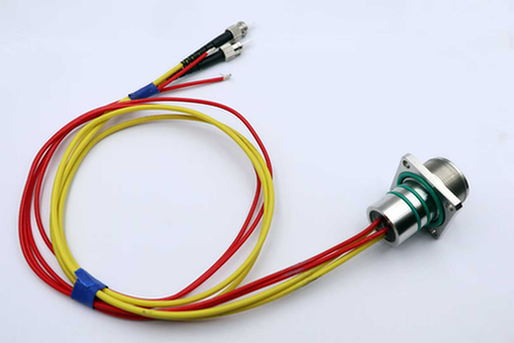
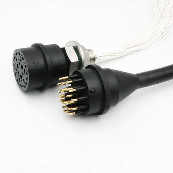
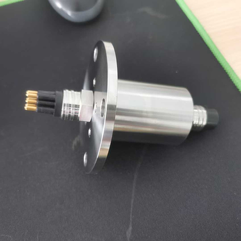
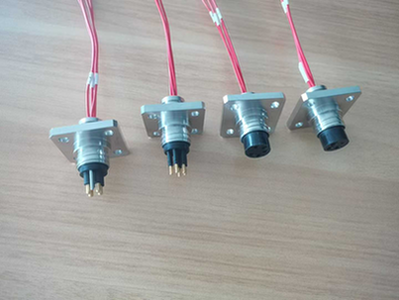
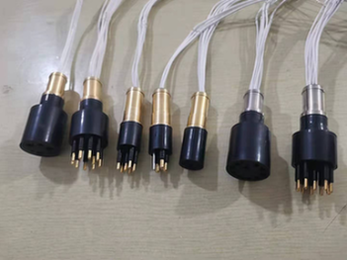
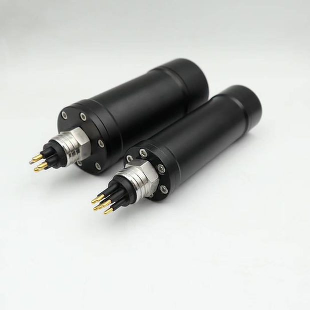
A hybrid underwater connector is a single connector assembly that combines:
– Electrical conductors for power transmission (AC or DC)
– Optical fibers for data communication
– Unified housing providing environmental protection for both
Visual Comparison:
Traditional Approach:          Hybrid Approach:
┌─────────────┐               ┌─────────────┐
│   Equipment │               │   Equipment │
│             │               │             │
│  [Power]═══╪═══[Power]      │             │
│  [Data]════╪═══[Data]       │  [Hybrid]═══╪═══[Hybrid]
│             │               │  (Power+Data)│
└─────────────┘               └─────────────┘
     2 connectors                   1 connector
     2 penetrations                 1 penetration
     2x installation time          1x installation time
1.2 Historical Development
Timeline of Hybrid Connector Evolution:
| Era | Development | Key Innovation |
|---|---|---|
| 1980s | First prototypes | Military applications |
| 1990s | Commercial introduction | Oil & gas adoption |
| 2000s | Standardization begins | IEC specifications |
| 2010s | Mainstream acceptance | Offshore wind entry |
| 2020s | Technology maturation | High-density designs |
Driving Forces:
– Subsea equipment complexity increasing
– Space constraints on underwater vehicles
– Cost pressure from project owners
– Reliability requirements tightening
1.3 Core Benefits
System Integration Advantages
Reduced Penetration Points:
Every hull penetration represents a potential failure point. Hybrid connectors consolidate connections:
| Configuration | Penetrations | Failure Risk Index |
|---|---|---|
| Separate (4 power + 4 fiber) | 8 | 100% (baseline) |
| Hybrid (combined) | 1 | 12.5% |
Installation Efficiency:
| Task | Separate Connectors | Hybrid Connector | Time Savings |
|---|---|---|---|
| Hull preparation | 8 holes | 1 hole | 87% |
| Connector installation | 8x operations | 1x operation | 87% |
| Testing and validation | 8x tests | 1x test | 87% |
| Total installation time | 16 hours | 4 hours | 75% |
Based on typical ROV tooling installation
Cost Benefits
Direct Cost Comparison:
| Cost Component | Separate Approach | Hybrid Approach | Savings |
|---|---|---|---|
| Connector hardware (8x vs 1x) | $3,200 | $1,800 | 44% |
| Installation labor | $2,400 | $600 | 75% |
| Testing and commissioning | $800 | $200 | 75% |
| Maintenance (annual) | $400 | $150 | 62% |
| Total First Year | $6,800 | $2,750 | 60% |
Lifecycle Cost Analysis (10 years):
| Scenario | Total Cost of Ownership |
|---|---|
| Separate connectors | $12,500 |
| Hybrid connector | $5,200 |
| Savings | 58% |
Note: Includes replacement costs, downtime, and maintenance
Reliability Improvements
Failure Mode Reduction:
Fewer components = fewer failure modes:
| Failure Mode | Separate (8 connectors) | Hybrid (1 connector) |
|---|---|---|
| Seal degradation | 8 potential points | 1 potential point |
| Contact corrosion | 8 potential points | 1 potential point |
| Cable strain relief | 8 potential points | 1 potential point |
| Installation error | 8x opportunities | 1x opportunity |
Field Performance Data:
Based on 5-year field study of 2,000+ subsea connections:
| メートル | Separate Connectors | Hybrid Connectors |
|---|---|---|
| Mean Time Between Failure | 8.2 years | 12.4 years |
| Installation defects | 4.2% | 1.1% |
| Water ingress incidents | 2.8% | 0.6% |
| Maintenance interventions | 1.8/year | 0.4/year |
Chapter 2: Hybrid Connector Architecture
2.1 Internal Configuration
Cross-Section Anatomy:
┌─────────────────────────────────────────────┐
│           Hybrid Connector Cross-Section    │
├─────────────────────────────────────────────┤
│  ┌─────┐  ┌─────┐  ┌─────┐  ┌─────┐        │
│  │ PWR │  │ PWR │  │ OPT │  │ OPT │        │  ← Contact modules
│  └──┬──┘  └──┬──┘  └──┬──┘  └──┬──┘        │
│     │        │        │        │            │
│  ┌──┴────────┴────────┴────────┴──┐         │
│  │    Insulation & Separation      │         │  ← Dielectric barrier
│  └─────────────────────────────────┘         │
│  ┌─────────────────────────────────┐         │
│  │    Outer Housing (Titanium)     │         │  ← Pressure vessel
│  └─────────────────────────────────┘         │
│  ═══════════════════════════════════         │  ← Seal interface
└─────────────────────────────────────────────┘
2.2 Contact Module Types
Electrical Contact Configurations
Power Contact Options:
| Type | 現在の評価 | Voltage Rating | アプリケーション |
|---|---|---|---|
| Mini (Size 16) | 5-13A | 600V | Sensors, cameras |
| Standard (Size 12) | 13-23A | 600V | ROV tooling, lights |
| Power (Size 8) | 23-60A | 1000V | Thrusters, pumps |
| High Power (Size 4) | 60-150A | 1500V | AUV propulsion |
Signal Contact Options:
| Type | 頻度 | アプリケーション |
|---|---|---|
| Coaxial | DC-18 GHz | Video, RF signals |
| Twisted Pair | DC-100 MHz | Ethernet, control |
| Thermocouple | DC | Temperature sensing |
Optical Contact Configurations
Fiber Type Options:
| Fiber Type | Core Size | アプリケーション | Advantages |
|---|---|---|---|
| Single-mode (SMF) | 9μm | Long-distance, high bandwidth | Low loss, high capacity |
| Multi-mode (MMF) | 50/62.5μm | Short-distance, cost-sensitive | Easier termination |
| Expanded Beam | 9μm (effective) | Harsh environments | Contamination tolerant |
Fiber Count Configurations:
| Density | Fiber Count | Typical Applications |
|---|---|---|
| 低い | 2-4 fibers | Simple sensors, cameras |
| ミディアム | 4-12 fibers | ROV control, monitoring |
| 高い | 12-24 fibers | Subsea production, data centers |
| Ultra-High | 24-48 fibers | Observatory networks |
2.3 Housing and Protection
Material Selection:
| 素材 | デプス評価 | Corrosion Resistance | Weight | Cost Index |
|---|---|---|---|---|
| チタン・グレード5 | 6,000m | 素晴らしい | Light | 100 |
| Stainless Steel 316L | 2,000m | 非常に良い | ミディアム | 45 |
| Bronze (Al-Ni) | 1,000m | グッド | Heavy | 30 |
| PEEK Polymer | 500m | フェア | Light | 20 |
Protection Mechanisms:
- Primary Seal: O-ring or metal-to-metal seal at mating interface
- Secondary Seal: Backup O-ring for redundancy
- Potting Compound: Epoxy fill around contacts
- Pressure Compensation: Oil-filled housing for deep water
- Cathodic Protection: Sacrificial anodes for metal housings
2.4 Coupling Mechanisms
Mating System Types:
| Type | Operation | Torque Required | アプリケーション |
|---|---|---|---|
| Threaded | Screw-type | 高い | Permanent installations |
| Bayonet | Push-and-twist | ミディアム | Frequent mating |
| Push-Pull | Linear motion | 低い | ROV operations |
| Blind Mate | Self-aligning | None | Wet-mate systems |
Locking Features:
- Positive locking indicators (visual/audible)
- Torque-limiting tools for consistency
- Locking wire provisions for vibration resistance
- Secondary locking mechanisms for critical applications
Chapter 3: Selection Criteria and Methodology
3.1 Step-by-Step Selection Process
Decision Tree:
                    START: Define Application
                            │
                            ▼
              ┌─────────────────────────┐
              │  What is max depth?     │
              │  <500m → Consider PEEK  │
              │  <2000m → SS 316L       │
              │  >2000m → Titanium      │
              └───────────┬─────────────┘
                          ▼
              ┌─────────────────────────┐
              │  Power requirements?    │
              │  Voltage: ___ V         │
              │  Current: ___ A         │
              │  Conductors: ___        │
              └───────────┬─────────────┘
                          ▼
              ┌─────────────────────────┐
              │  Data requirements?     │
              │  Fiber type: SM/MM      │
              │  Fiber count: ___       │
              │  Data rate: ___ Gbps    │
              └───────────┬─────────────┘
                          ▼
              ┌─────────────────────────┐
              │  Mating frequency?      │
              │  Permanent → Dry-mate   │
              │  Frequent → Wet-mate    │
              └───────────┬─────────────┘
                          ▼
              ┌─────────────────────────┐
              │  Environmental factors? │
              │  Temperature range      │
              │  Chemical exposure      │
              │  UV exposure            │
              └───────────┬─────────────┘
                          ▼
                    SELECT CONNECTOR
3.2 Electrical Specifications
Voltage and Current Requirements
Key Considerations:
- Operating Voltage:
- Nominal system voltage
- Maximum transient voltage
- Insulation coordination
- Current Capacity:
- Continuous current rating
- Peak/intermittent current
- Derating for temperature and depth
- Voltage Drop:
- Conductor size selection
- Cable length considerations
- Power loss calculations
Sizing Formula:
Conductor Size (AWG) = f(Current, Length, Allowable Drop)

Example Calculation:
- Current: 10A
- Cable Length: 100m
- Allowable Drop: 3%
- System Voltage: 48V DC

Required: 8 AWG conductor (minimum)
Contact Resistance
Acceptable Values:
| Contact Type | Initial Resistance | Maximum After Testing |
|---|---|---|
| Power (Size 8) | <5 mΩ | <10 mΩ |
| Signal (Size 16) | <10 mΩ | <20 mΩ |
| Coaxial | <5 mΩ (center) | <10 mΩ |
Testing Standards:
– MIL-DTL-38999 (military)
– IEC 60512 (industrial)
– ISO 13628-6 (subsea)
3.3 Optical Specifications
Fiber Type Selection
Single-Mode vs. Multi-Mode:
| パラメータ | Single-Mode | Multi-Mode |
|---|---|---|
| Core Diameter | 9μm | 50/62.5μm |
| Wavelength | 1310/1550nm | 850/1300nm |
| 帯域幅 | High (10+ Gbps) | Medium (1-10 Gbps) |
| Distance | >10 km | <2 km |
| コスト | Higher | Lower |
| Termination | More difficult | Easier |
Selection Guide:
| 申し込み | Recommended Fiber | 根拠 |
|---|---|---|
| Long-distance telemetry | Single-mode | Low attenuation |
| Video transmission | Single-mode | High bandwidth |
| Short control links | Multi-mode | Cost effective |
| Harsh environment | Expanded beam | Contamination tolerance |
Optical Performance Requirements
Key Parameters:
| パラメータ | Typical Value | Maximum Acceptable |
|---|---|---|
| Insertion Loss | 0.3-0.5 dB | 0.75 dB |
| Return Loss | >50 dB | >40 dB |
| Channel Uniformity | ±0.1 dB | ±0.3 dB |
| Crosstalk | <-60 dB | <-50 dB |
Testing Requirements:
– OTDR trace for each fiber
– Insertion loss measurement (bi-directional)
– Return loss verification
– Visual inspection (end-face geometry)
3.4 Environmental Specifications
Depth and Pressure
Pressure Ratings:
| 深さ | Pressure | Typical Applications |
|---|---|---|
| 300m | 30 bar | Shallow water, ROVs |
| 1,000m | 100 bar | Coastal, aquaculture |
| 2,000m | 200 bar | Offshore oil & gas |
| 3,000m | 300 bar | Deepwater production |
| 6,000m | 600 bar | Full ocean depth |
Derating Considerations:
Pressure cycling affects connector life:
| Cycling Frequency | Life Reduction Factor |
|---|---|
| Static (no cycling) | 1.0 (baseline) |
| Occasional (<10/year) | 0.95 |
| Regular (10-100/year) | 0.85 |
| Frequent (>100/year) | 0.70 |
Temperature Range
Operating Temperature Classes:
| Class | Temperature Range | アプリケーション |
|---|---|---|
| スタンダード | -20°C to +60°C | General purpose |
| Extended | -40°C to +85°C | Arctic, tropical |
| High Temp | -20°C to +125°C | Near equipment |
| Cryogenic | -196°C to +60°C | Special applications |
Thermal Effects:
- Material expansion/contraction affects seal integrity
- Optical performance varies with temperature
- Contact resistance increases at temperature extremes
- Lubricant viscosity changes affect mating
Chemical and UV Exposure
Chemical Resistance Matrix:
| Housing Material | Seawater | Oil | Hydraulic Fluid | H₂S |
|---|---|---|---|---|
| チタン | 素晴らしい | 素晴らしい | 素晴らしい | 素晴らしい |
| SS 316L | 非常に良い | グッド | グッド | フェア |
| ブロンズ | グッド | フェア | フェア | Poor |
| PEEK | 素晴らしい | 素晴らしい | グッド | グッド |
UV耐性:
- Most metal housings: Inherently UV resistant
- Polymer components: Require UV stabilizers
- Cable jackets: Specify UV-resistant compounds
- Recommendations: Protective covers for long-term exposure
3.5 Mechanical Specifications
Mating Cycle Requirements
Cycle Life Expectations:
| 申し込み | Expected Cycles | Recommended Rating |
|---|---|---|
| Permanent installation | 1-5 | 50 cycles |
| Occasional maintenance | 10-50 | 100 cycles |
| Regular intervention | 50-500 | 500 cycles |
| ROV tooling | 500-2000 | 2000+ cycles |
Wear Indicators:
- Visual inspection marks
- Torque value changes
- Insertion force measurements
- Electrical contact resistance trending
Cable Retention
Strain Relief Requirements:
| Cable Type | Minimum Bend Radius | Pulling Tension |
|---|---|---|
| Power cable (heavy) | 10x diameter | 500 N |
| Power cable (light) | 8x diameter | 300 N |
| Fiber optic | 15x diameter | 150 N |
| Hybrid cable | 12x diameter | 400 N |
Retention Mechanisms:
- Cable glands with compression seals
- Epoxy potting for permanent installations
- Mechanical clamps for field termination
- Kevlar tension members for fiber
Chapter 4: Application-Specific Recommendations
4.1 ROV and AUV Systems
Typical Requirements:
| パラメータ | 検査用ROV | Work-Class ROV | AUV |
|---|---|---|---|
| 深さ | 300-1000m | 3000-4000m | 1000-6000m |
| Power | 100-500W | 5-50kW | 500W-5kW |
| Data | 1-2 fibers | 4-12 fibers | 2-8 fibers |
| Mating | Frequent | Frequent | Occasional |
Recommended Configurations:
Inspection ROV:
– Housing: Stainless Steel 316L
– Power: 4x Size 12 contacts (23A each)
– Data: 4x single-mode fibers
– Coupling: Bayonet (quick connect)
– Rating: 1000m, 500 mating cycles
Work-Class ROV:
– Housing: Titanium Grade 5
– Power: 4x Size 8 contacts (60A each)
– Data: 12x single-mode fibers
– Coupling: Threaded with secondary lock
– Rating: 4000m, 2000 mating cycles
4.2 Offshore Wind Applications
Turbine Monitoring:
| パラメータ | 必要条件 | 根拠 |
|---|---|---|
| デザイン・ライフ | 25+ years | Match turbine lifespan |
| 深さ | 0-100m | Foundation monitoring |
| 環境 | Splash zone | High corrosion risk |
| Maintenance | Minimal | Difficult access |
Recommended Specifications:
– Housing: Super Duplex Stainless Steel
– Power: 4x Size 16 contacts (sensor power)
– Data: 4-8x single-mode fibers
– Protection: Enhanced corrosion coating
– Rating: 100m, 25-year design life
Substation Connections:
- Higher fiber counts (24-48 fibers)
- Higher power capacity (up to 600V)
- Wet-mate capability for diver intervention
- Redundant sealing systems
4.3 Subsea Production Systems
Critical Requirements:
| パラメータ | 仕様 | Importance |
|---|---|---|
| Reliability | 99.9%+ uptime | Production continuity |
| 深さ | Up to 3000m | Deepwater fields |
| 温度 | Up to 125°C | Near wellhead |
| Life | 20-30 years | Field lifespan |
Recommended Approach:
– Premium wet-mate hybrid connectors
– Titanium housing with metal seals
– Redundant contact systems
– Extensive qualification testing
– Manufacturer support and spares
4.4 Scientific and Research Applications
Ocean Observatory:
| 必要条件 | 仕様 |
|---|---|
| 深さ | Full ocean depth (6000m) |
| Life | 10+ years unattended |
| Data | High bandwidth (10+ Gbps) |
| Power | Moderate (100-500W) |
Recommended Configuration:
– Housing: Titanium with pressure compensation
– Power: 4-8x Size 12 contacts
– Data: 12-24x single-mode fibers
– Coupling: Dry-mate (permanent) or wet-mate (intervention)
– Testing: Full qualification to 6000m
Chapter 5: Installation and Commissioning
5.1 Pre-Installation Checklist
Documentation Review:
- [ ] Connector datasheet and specifications
- [ ] Installation procedure from manufacturer
- [ ] Torque specifications
- [ ] Testing requirements
- [ ] Safety procedures
Visual Inspection:
- [ ] Housing condition (no dents, scratches)
- [ ] Seal condition (no cuts, deformation)
- [ ] Contact condition (no corrosion, damage)
- [ ] Cable condition (no kinks, damage)
- [ ] Markings legible and correct
Cleaning Requirements:
| Component | Cleaning Method | 頻度 |
|---|---|---|
| Housing exterior | Fresh water rinse | Before each install |
| Seal surfaces | Lint-free wipe + alcohol | Before each install |
| Optical contacts | Specialized fiber cleaner | Before each install |
| Electrical contacts | Contact cleaner | Before each install |
5.2 Installation Procedures
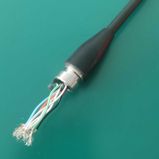
Cable Preparation
Step-by-Step:
- Measure and mark cable length
- Strip outer jacket to specified length
- Prepare shield (if applicable)
- Strip individual conductors
- Terminate electrical contacts (crimp or solder)
- Prepare fiber (strip, cleave, terminate)
- Assemble connector per manufacturer instructions
- Apply strain relief and sealing
Critical Dimensions:
Cable Preparation Example:
┌────────────────────────────────────────┐
│                                        │
│  Outer Jacket Strip: 150mm             │
│  Shield Trim: 140mm                    │
│  Conductor Strip: 8mm                  │
│  Fiber Buffer Strip: 40mm              │
│                                        │
└────────────────────────────────────────┘
Connector Mating
Proper Mating Technique:
- Align connector halves using guide keys
- Engage smoothly without forcing
- Rotate (if threaded) until hand-tight
- Torque to specification with calibrated tool
- Verify locking mechanism engaged
- Record torque value for quality tracking
Torque Specifications (Example):
| Connector Size | Minimum Torque | Maximum Torque |
|---|---|---|
| Size 16 | 2.5 Nm | 3.0 Nm |
| Size 12 | 4.0 Nm | 5.0 Nm |
| Size 8 | 8.0 Nm | 10.0 Nm |
Common Mistakes to Avoid:
- ❌ Cross-threading (misalignment during engagement)
- ❌ Over-torquing (damages seals and threads)
- ❌ Under-torquing (incomplete seal compression)
- ❌ Contamination (dirt, grease on seals)
- ❌ Cable twist (stress on terminations)
5.3 Testing and Validation
Electrical Testing
Required Tests:
| Test | 方法 | Acceptance Criteria |
|---|---|---|
| Continuity | Multimeter | <1 Ω per conductor |
| Insulation Resistance | Megger (500V) | >100 MΩ |
| Contact Resistance | Milliohm meter | <10 mΩ |
| Hi-Pot | Dielectric tester | No breakdown at 1500V |
Optical Testing
Required Tests:
| Test | Equipment | Acceptance Criteria |
|---|---|---|
| Insertion Loss | Light source + power meter | <0.75 dB per connection |
| Return Loss | OTDR or return loss meter | >40 dB |
| End-face Inspection | Fiber microscope | IEC 61300-3-35 compliant |
Pressure Testing
Factory vs. Field:
| Test Type | Pressure | 期間 | 申し込み |
|---|---|---|---|
| Factory (all) | 1.5x rated | 24 hours | Quality assurance |
| Field (critical) | 1.1x rated | 4 hours | Before deployment |
| Field (routine) | Visual only | – | Regular maintenance |
Chapter 6: Maintenance and Troubleshooting
6.1 Preventive Maintenance Schedule
Recommended Intervals:
| アクティビティ | 頻度 | Critical Applications |
|---|---|---|
| 目視検査 | Every 6 months | Every 3 months |
| Electrical testing | 毎年 | Every 6 months |
| Optical testing | 毎年 | Every 6 months |
| Seal replacement | Every 5 years | Every 3 years |
| Complete overhaul | Every 10 years | Every 5 years |
Inspection Checklist:
- [ ] Housing condition (corrosion, damage)
- [ ] Seal condition (cuts, compression set)
- [ ] Cable condition (chafing, kinks)
- [ ] Marking legibility
- [ ] Locking mechanism function
- [ ] Contact condition (if accessible)
6.2 Common Failure Modes
Water Ingress
Symptoms:
– Insulation resistance degradation
– Intermittent electrical connections
– Optical signal loss
– Visible moisture inside housing
Root Causes:
– Damaged or missing seals
– Improper installation (under-torqued)
– Seal compression set (age)
– Housing damage
Corrective Actions:
1. Retrieve connector
2. Dry thoroughly (controlled environment)
3. Replace all seals
4. Inspect contacts for corrosion
5. Re-terminate if necessary
6. Pressure test before redeployment
Contact Corrosion
Symptoms:
– Increased contact resistance
– Intermittent connections
– Visible corrosion on contacts
Root Causes:
– Seal failure allowing seawater entry
– Galvanic corrosion (dissimilar metals)
– Contamination during installation
予防だ:
– Use compatible materials
– Apply dielectric grease (if approved)
– Ensure proper seal compression
– Regular inspection and cleaning
Fiber Breakage
Symptoms:
– Complete signal loss on one or more fibers
– High insertion loss
– OTDR shows break location
Root Causes:
– Excessive bend radius violation
– Cable tension during installation
– Vibration fatigue
– Manufacturing defect
予防だ:
– Respect minimum bend radius
– Proper strain relief
– Vibration damping if needed
– Careful handling during installation
6.3 Troubleshooting Guide
Problem: Intermittent Electrical Connection
| Possible Cause | Diagnostic | Solution |
|---|---|---|
| Loose connection | Check torque value | Re-torque to spec |
| Contact corrosion | Measure resistance | Clean or replace contacts |
| Cable damage | 目視検査 | Replace cable assembly |
| Seal failure | Insulation test | シールの交換 |
Problem: High Optical Insertion Loss
| Possible Cause | Diagnostic | Solution |
|---|---|---|
| Dirty end-faces | Microscope inspection | Clean with fiber cleaner |
| ミスアライメント | Check connector mating | Remate properly |
| Fiber damage | OTDR trace | Replace fiber assembly |
| Bend radius violation | 目視検査 | Reroute cable |
Problem: Water Ingress Detected
| Possible Cause | Diagnostic | Solution |
|---|---|---|
| Damaged seal | 目視検査 | Replace seal |
| Under-torqued | Check torque history | Re-torque, replace seal |
| Housing crack | Dye penetrant test | Replace housing |
| Cable entry failure | 目視検査 | Re-terminate cable |
Chapter 7: Supplier Selection and Qualification
7.1 Evaluation Criteria
Technical Capabilities:
| Criterion | Weight | Evaluation Method |
|---|---|---|
| Product range | 15% | Catalog review |
| Technical support | 20% | Reference calls |
| Custom engineering | 15% | Past project review |
| 試験施設 | 15% | Facility audit |
| Quality certifications | 20% | Certificate review |
| Delivery performance | 15% | Customer references |
Commercial Considerations:
| Criterion | Weight | Evaluation Method |
|---|---|---|
| Price competitiveness | 25% | Quote comparison |
| Payment terms | 15% | Contract negotiation |
| Warranty terms | 20% | Terms review |
| リードタイム | 20% | Commitment review |
| After-sales support | 20% | Service level agreement |
7.2 Qualification Process
Stage 1: Desktop Review
– Company background and financial stability
– Product certifications and qualifications
– Customer references in similar applications
– Quality management system certification
Stage 2: Technical Evaluation
– Product testing (sample units)
– Engineering support assessment
– Custom capability review
– Documentation quality
Stage 3: Facility Audit
– Manufacturing capabilities
– Testing equipment and procedures
– Quality control processes
– Traceability systems
Stage 4: Trial Order
– Small quantity order for field evaluation
– Performance monitoring
– Support responsiveness
– Issue resolution capability
7.3 Red Flags to Watch For
Warning Signs:
- ❌ Reluctance to provide test data
- ❌ No in-house testing facilities
- ❌ Vague warranty terms
- ❌ Poor communication response time
- ❌ No references in your application sector
- ❌ Unwillingness to sign NDA
- ❌ Prices significantly below market (quality concerns)
- ❌ No engineering support offered
Chapter 8: Future Trends and Developments
8.1 Technology Roadmap
Near-Term (2026-2028):
- Higher fiber counts in same form factor
- Improved wet-mate reliability
- Smart connectors with health monitoring
- Expanded beam technology mainstream adoption
Mid-Term (2028-2030):
- Integrated sensors (temperature, pressure, humidity)
- Wireless data transfer for health monitoring
- Additive manufacturing for custom housings
- Self-healing seal technologies
Long-Term (2030+):
- Fully optical (no electrical) for certain applications
- Bio-inspired self-cleaning surfaces
- Quantum communication compatibility
- Autonomous mating systems for AUVs
8.2 Market Dynamics
Growth Drivers:
- Offshore Wind Expansion
- 200+ GW target by 2030
- Each turbine requires 8-12 hybrid connections
- Foundation monitoring drives sensor networks
- Subsea Data Infrastructure
- Underwater data centers
- Edge computing at sea
- High-bandwidth sensor networks
- Autonomous Systems
- AUV fleet expansion
- Underwater docking stations
- Rapid charging and data transfer
- Oil & Gas Digitalization
- All-electric subsea systems
- Real-time monitoring
- Extended reach tiebacks
8.3 Standards Development
Ongoing Standardization:
- IEC 61754: Fiber optic connector interfaces (underwater variants)
- ISO 13628: Subsea production systems (connector requirements)
- API 17F: Subsea production control systems
- NORSOK: Subsea equipment requirements (Norwegian standard)
Industry Initiatives:
- Subsea Connect: Interoperability working group
- Ocean Observatories Initiative: Research connector standards
- Offshore Wind Connector Forum: Application-specific guidelines
結論
Hybrid underwater connectors represent a mature, cost-effective solution for modern subsea systems requiring both power and data connectivity. Proper selection requires careful consideration of electrical, optical, environmental, and mechanical requirements, balanced against application-specific constraints and lifecycle cost considerations.
Key Selection Principles:
- Match connector to application – Don’t over-specify or under-specify
- 総所有コストを考える – Not just purchase price
- Plan for the full lifecycle – Installation, maintenance, replacement
- Qualify your suppliers – Technical capability and support matter
- Follow best practices – Proper installation prevents most failures
As subsea operations become more complex and demanding, hybrid connectors will continue gaining market share, driven by their inherent advantages in integration, reliability, and cost-effectiveness.
References and Sources
- IEC 60512: Connectors for electronic equipment – Tests and measurements
- ISO 13628-6: Subsea production systems – Subsea production control systems
- MIL-DTL-38999: Circular electrical connector specification
- Subsea Connect Industry Survey 2026
- Offshore Wind Connector Forum Technical Guidelines
- Manufacturer technical datasheets and application notes
- Field performance databases from major operators
- IEEE Journal of Oceanic Engineering technical papers
About This Guide:
This selection guide was prepared by HYSF Subsea’s engineering team, combining product expertise with field experience from hundreds of installations. For application-specific recommendations or custom connector solutions, contact our engineering team at [email protected].
Related Resources:
– 技術仕様ガイド
– インストレーション&メイティングガイド
– Custom Engineering Services
– お問い合わせ